The Idea - Design Considerations - Electrical Design - Optical Design - Power Supply - Mechanical Design and Enclosure - Camera Mount - Camera Firmware Server Software
The Idea
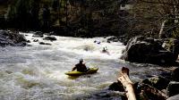
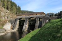
The idea arose out of one of our hobbies: Whitewater kayaking on the river Murg in the northern Black Forest, Germany. Kayaking there heavily depends on river flows and is only possible during heavy rain and snowmelt. Additionally, multiple hydroelectric dams and power plants along the river influence the flow. While several gauges are accessible online, they are positioned between the dams in such a way that oftentimes the actual flows encountered while kayaking cannot be reliably predicted. Out of this predicament, the idea of setting up an autonomous Internet-connected camera was born.
While off-grid outdoor cameras are widely available in various price segments, most of them serve one of the following purposes:
- Security: These cameras have motion detection and, when activated start recording a video which is then sent to a predetermined recipient either via WiFi or the cell network. Activation is usually a rare occurance and so, not much power is needed.
- Wildlife recording: These cameras work similar to security cameras, but usually have no network connectivity and just store the video on an SD card. Since the power budget does not include any radio devices, very little power is needed.
For our use case, the requirements are different:
- No motion sensor is required. Time-based activation is sufficient
- Still images every 30min to 1h are sufficient. Video recording is not needed.
- Net connectivity: The pictures taken need to be published on the Internet immediately to be useful to the community.
- No grid power: Power must be supplied by batteries or solar cells as the camera will be located in the middle of a forest.
- Endurance: Due to the inaccessibility location of the camera, the time between battery replacements / maintenance visits should be as long as possible. At least one month, but preferably as long as possible.
- Low cost: As the camera is well hidden but still publicly accessible, theft or vandalism is not expected, but certainly within the realm of possibility.
After much research, no product could be found that meets all of the above requirements. So the decision was made to design one from scratch.
Design Considerations
For the design, two core components are required:
- Still Camera with a medium to low resolution (<4MP) as this provides enough details to estimate the river flow
- Cell network connectivity. Slow speeds are acceptable since not much data needs to be transferred. As all network providers in Germany have made a commitment to leave 2G networks operational for the coming years, GPRS connectivity was determined to be sufficient as these modules are usually available very cheaply.
Nowadays, thanks to the world wide maker movement, serveral development platforms, are readily, cheaply available. On first sight, they lend themselves almost perfectly to this project:
- Arduino with additions such as ArduCam and various GSM modules/“hats”.
- Espressif ESP32: Here, ESP32-CAM as well as the LILYGO TTGO T-Call for GSM are availabe.
After some evaluation, several shortcomings with these solutions were found:
- Most of the available designs use power supply components that are very inefficient and wired in a way that unnecessary power is drawn constantly, even when the device is inactive. Since battery live needs to be maximized, this would need to be mitigated by additional power switching components and logic.
- The optical components are of very low quality and mostly use a fixed lens with an unacceptable focal length.
- Especially Arduino based solutions are very slow and make use of the use of addtional components such as FPGAs and RAM to buffer the incoming fast data from the fast CCD sensor. This makes them expensive and unnecessarily complicated.
Due to these findings, it was decided to design a system from scratch.
Electrical Design
The system is loosely based on the following products of which schematics are publicly available:
- LILYGO TTGO T-Call with the SIM800L quad-band GSM/GPRS module
- ESP32-CAM with the OV2640 image sensor (UXGA 1600x1200 with embedded JPEG compression)
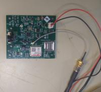
A custom 4-layer circuit board was designed that holds all components except for the CCD image sensor which is connected with a ribbon cable.
- A ESP32-S2 SoC instead of the older ESP32 was used. While only having one core, this architecture provides more GPIO ports.
- None of the Espressif ESP32 development modules such as Wroom or Wrover were used. Instead a bare-bones QFN48 ESP32-S2 IC was chosen. This gives full control of the amount of RAM, flash, as well as what peripherials are used and how they are wired.
- The always-on main voltage of 3.3V is generated by a high-quality, highly efficient automotive buck converter which accepts voltages up to 15V, perfect for operation with a 12V lead-acid or LiFePo4 battery.
- Various auxiliary voltages for the image sensor and the GMS module are generated by cheaper buck converters or LDOs. These can be controlled by additional low-power CMOS-switches and are only activated by the microcontroller when needed.
- Current / voltage sensors were added to be able to remotely monitor the state of the battery and/or the solar cells.
- Protective circuitry was added to prevent a wrongly connected battery from destroying the system.
- A cheap SIM800C GPRS module as well as a sim card holder are placed directly on the board. While GPRS is very old and slow, it is enough to quickly transfer a single JPEG compressed image. While many countries are already phasing out their 2G networks, German operators have committed to keeping them active.
- Antenna connectors for GSM (SIM800C) and 802.11bgn WiFi (ESP32-S2) were added. This allows for external antennas. Since the location of the camera will be in a mountainous, remote area, usage of a high-gain antenna might prove necessary.
The board was created entirely using KiCad 4
With the selected components, a sleep current of 15uA could be achieved.

Optical Design
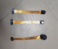
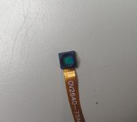
The system uses an OV2640 CCD sensor which has a resolution of 16200x1200 pixel and supports on-board JPEG compression. They can be obtained cheapy from EBay, AliExpress and other sources and directly connected to the ESP32-S2 via its camera interface. Usually a small, fixed lens of some sort is glued to the platic enclosure. Tests have shown that the fixed lenses are unpractical for the situation at hand as the level of zoom is too small and image distortion is quite noticable.
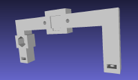
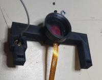
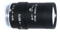
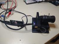
The decision was made to design a lens holder and use it in conjunction with a CCTV manual zoom lens, which can also be obtained cheaply from various sources. The final lens holder consists of a custom-designed 3D printed frame which holds to the sensor and an off-the-shelf metal CS-mount lens receptacle. Latter includes an IR-cut filter which filters out unwanted wavelengths from the sunlight that would otherwise distort the colors of the photo.
Power Supply
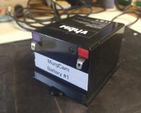
For the time being, a 6Ah 12.3V LiFePo4 battery pack was chosen as power supply. This battery pack nicely fits into the selected enclosure and thus, no additional space is needed. Size of the installation is kept to a minimum.
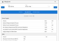
Two battery packs were purchased. The remaining voltage of the installed battery is measured and transmitted with each taken photo. Thus a change of battery can be scheduled accordingly.
The later addition of solar panels or a bigger battery is possible. Solar panels might prove inefficient as most of the sky is blinded by large rocks and trees. A larger battery could be added by installing a waterproof electrical enclosure.
Mechanical Design and Enclosure
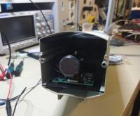
An initial design goal was to keep the size of the camera to a minimum. Many kinds of empty camera enclosures of varying quality are offered on EBay, AliExpress etc. Afer some consideration, a model that provides just enough space for the camera module and the battery pack was selected. After delivery, the base plates for the battery and the camera were designed and 3D printed. The enclosure incooperates a continuous slot on the inside. The base plates were thus designed to fit this slot which resulted in a sliding mechanism which is especially convinient for battery changes.
Camera Mount
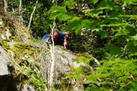
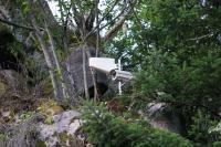
For the mount, 3/4" water pipes in combination with weather proof joints were used and cut to the required length on site. Two M10 heavy duty anchor bolts were driven into the rock to fasten the camera mount.
Camera Firmware
Normal Operation
The firmware is custom written for the project in C using the Espressif esp-idf SDK. The main focus was conservation of power. The camera makes heavy use of the deep sleep mode of the ESP32S2. In this mode all external components are switched off except for a timer circuit which reactivates the camera after a predetermined amount of time. During regular operation, the software works as follows:
- Controller is activated by deep sleep timer
- Image sensor, current/voltage sensors are activated
- Image sensor is configured
- Single photo is taken
- Image sensor is shut down
- GSM module is powered up and a connection to the camera server is established
- Picture and telemetry data (battery voltage etc.) are transmitted to server
- New camera settings and time until next photo is received from server and stored in non volatile memory
- GSM module and all other components are shut down
- Deep sleep mode is activated for the amount of time received from server
This mode of operation allows the camera to spend most time in a power-conserving deep sleep mode but still keeps the system flexible as the time until the camera wakes up can be set by the server every time a photo is taken. This allows for longer sleep times during the night and thus even higher energy efficiency. Since most of the timing logic is implemented on the server side, modifications to the timing are always possible by modifying the server software. If the server could not be reached for some reason, the camera defaults to a sleep time stored in flash memory.
Configuration Mode
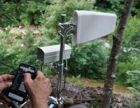
In addition to normal operation, the camera can be put into configuration mode. In this mode, A WiFi network AP is opened by the camera using the WiFi capabilities of the ESP32S2 chip. A simple web interface can be accessed to set the camera up (Exposure time, GPS PIN, APN etc.) and store the settings in the camera’s flash memory. All settings can also be modified remotely as each time a picture is transmitted, the server can pass new settings to the camera which overwrite the previous configuration and are stored in the flash memory.
Server Software
… to come …